Overview
Broadcast Devices IPC-800 Interlock Consolidation Panel
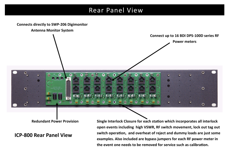
The IPC-800 Interlock consolidation/RF safety panel brings all interlock “event” connections to one closure per station connected to a combiner system. The system provides the status of RF presence on a transmission lines. Used in conjunction with BDI’s popular DPS-100D series RF power meters, the ICP-800 can be used with the SWP-206 Digi-Monitor Antenna Monitor System for complete interlock control and RF Safety status.
Features
The ICP-800 Interlock Consolidation panel, DPS-100D Series RF Power meter and The SWP-206 Digi Monitor were developed by BDI to display multiple —DPS-100D True RMS Digital Power Sensors in a single 2RU rack unit display.
No other RF monitor/protection system offers more flexibility than BDI’s comprehensive RF site products which also include temperature, transmission line pressure monitoring in addition to other site related GPIO closures that can be monitored for display.
Provides simple RF “Safe” - RF off condition or RF “ON for when RF is applied to any DPS-100D series power meter connected. RF On threshold is user defined at the connected DPS -100D series power meter. This provides site managers or tower crews with an easy to read display for RF safety programs. When the red light is out and green is illuminated it’s safe to climb. Because RF Safety is serious business and required the BDI IPC-800 panel can be part of an RF Safety plan for most any site with a combined system or to monitor multiple transmission lines . Even if interlock closures are not a factor you can connect up to 8 DPS -100D series power meters to each panel for positive indication of all transmission lines on a given tower.
Need more detail about RF operation? Add the BDI Panel Viewer soft ware package to multi ple BDI DPS -100D series RF power meters for inspection of forward and refl ected power, internal and optional external temperature sensors for each meter, transmission line pressure and the condition of 6 general purpose input/output closures. Viewable Internet connection by multiple users simultaneously if desired anywhere in the world.

Specifications / Documents
![]()
![]()
- Number of Channels: 16 DPS-100D series power meters can be connected lights provided for 8 meters. The other 8 meter provision is for connecti on to an interlock loop such as combiner or system reject loads, lock out tag out switches, patch panels or RF switches
- Number of interlock closures: 8—consolidated interlock closures
- Indicators: 8 RF ON and 8 SAFE -(RF off ) test switch provided for each channel to test indicator lights for proper operation. 2—power indicators
- Other connections: DSUB connector provided for interface to SWP-206 interlock relay outputs, Jumpers for bypass of a DPS-100D power meter for maintenance/troubleshooting
- Controls: 8 toggle switches for test of indicators. When turned on both indicator lights illuminate for testing
- Power Requirements: 12 VDC@ 2A redundant power inputs—12 VDC power supplies are supplied with each system. Provision to connect to 2 –external 12 VDC power supplies
- Mechanical Specifications: 19” L X 3.5” H—standard 2 RU EIA rack panel four 4 mounting holeles provided for installation in any standard EIA rack enclosure
- Weight and Shipping Information: 4 lbs. including carton, carton size 25” X 4” X 4”
- Environmental Conditions Required: 0-55 degrees C. non condensing atmosphere