Overview
Henry
Henry Series 80 PowerClamp Surge Suppressors (See full page)
Henry Engineering introduces the PowerClamp series of Transient Voltage Surge Suppression (TVSS) units by Sine Control Technology, Inc. Thousands of these highly effective TVSS units have been in use since the early 1980’s in the defense*, medical, petroleum, and manufacturing industries. Their superb performance and reliability is now available to the broadcasting industry. (*Sine Control has been selected as a Justified Sole Source supplier of TVSS units to the United State Department of Defense.)
Sophisticated broadcast equipment demands clean power. Power line spikes, surges, and waveform distortions will produce system reliability problems, data errors, intermittent or unexplainable operation, computer lockups and failures. PowerClamp TVSS units virtually eliminate the power line spikes and surges that cause these malfunctions and failures.
PowerClamp TVSS units are the most advanced TVSS units in the industry. Their unique design utilizes multi-stage hybrid circuitry to yield clamping levels as low as 2 volts above the AC waveform. Where other units won’t clamp a surge until it’s 500-800 volts above normal voltage, PowerClamp TVSS units instantly attenuate surges within a few volts of the AC waveform. Their highly effective surge suppression and waveform tracking results in superior AC waveform integrity, i.e., “clean power” without spikes, surges, noise, harmonics, or distortion.
PowerClamp TVSS units are designed specifically for broadcast applications. They are ideal for installation at transmitter sites where massive power surges and lightning-induced transients are a major cause of transmitter unreliability and damage. PowerClamp units will drastically reduce tripped breakers, transmitter shutdowns, and prevent or minimize damage to transmitting equipment caused by such power surges.
PowerClamp TVSS units should also be installed at studio locations to prevent power line problems from causing malfunctions and damage to audio/video equipment and computers. PowerClamp units will eliminate power line spikes from entering a facility from the main AC feed line. Their bi-directional design will also prevent power line noise, spikes, and disturbances generated within the facility from being distributed to other equipment.
PowerClamp TVSS units are always installed IN PARALLEL with AC feed lines. They suppress power line spikes and surges by shunting them to ground. PowerClamp units do not need to be “matched” to the equipment they are protecting, nor do they introduce any loss in the line.
The new Series 80 and Series 200 PowerClamp units now offer higher surge-amp capacity, internal LED status indicators, and UL-Listed weatherproof enclosures suitable for indoor or outdoor installation.
![]()
A certified Electrician should provide assistance in choosing the correct unit
| Model | Service Type | Surge Joules Per Ø | Surge Amps 20 microsec | Modes of Protection | Connection Wiring |
| HP80-1 | 120/240V 1Ø | 1,344 | 80,000 | L-L/L-N/L-G | 2-L, 1-G |
| *HP80-2 | 120/240V 1Ø | 1,344 | 80,000 | L-L/L-N/L-G/N-G | 2-L, 1-N, 1-G |
| HP80-3 | 120/208V 3Ø WYE | 1,344 | 80,000 | L-L/L-N/L-G | 3-L, 1-G |
| *HP80-4 | 120/208V 3Ø WYE | 1,344 | 80,000 | L-L/L-N/L-G/N-G | 3-L, 1-N, 1-G |
| HP80-7 | 277/480V 3Ø WYE | 3,565 | 80,000 | L-L/L-N/L-G | 3-L, 1-G |
| *HP80-8 | 277/480V 3Ø WYE | 3,565 | 80,000 | L-L/L-N/L-G/N-G | 3-L, 1-N, 1-G |
L-L = line to line; L-N = line to neutral; L-G = line to ground; N-G = neutral to ground common mode*
*With Neutral-to-Ground Common Mode protection: needed when not installed at main panel where Neutral and Ground are tied.
- Response time: 1-2 nanoseconds
- Maximum leakage current: 6mA/phase
- Fusing: One fuse per phase with failure indicator LEDs
- Minimum Humidity Range: 5% to 97%
- Operating temperature: -20ºC (-68º F) to 70º C (158º F) ambient temperature
- Dimensions: (all units) 6" wide, 6" high, 4" deep
- Shipping weight: approximately 5 lbs. (including packaging)
- 5 Year pro-rated Limited Replacement Warranty
![]()
A certified Electrician should provide assistance in choosing the correct unit
| Model | Service Type | Surge Joules Per Ø | Surge Amps 20 microsec | Modes of Protection | Connection Wiring |
| HP200-1-TX | 120/240V 1Ø | 3,350 | 200,000 | L-L/L-G | 2-L, 1-G |
| *HP200-2 | 120/240V 1Ø | 3,350 | 200,000 | L-L/L-N/L-G/N-G | 2-L, 1-N, 1-G |
| HP200-3 | 120/208V 3Ø WYE | 3,350 | 200,000 | L-L/L-G | 3-L, 1-G |
| *HP200-4 | 120/208V 3Ø WYE | 3,350 | 200,000 | L-L/L-N/L-G/N-G | 3-L, 1-N, 1-G |
| HP200-7 | 277/480V 3Ø WYE | 10,185 | 200,000 | L-L/L-G | 3-L, 1-G |
| *HP200-8 | 277/480V 3Ø WYE | 10,185 | 200,000 | L-L/L-N/L-G/N-G | 3-L, 1-N, 1-G |
| *HP200-9 | 120 HI LEG/208 3Ø WYE | 10,185 | 200,000 | L‐L/L‐N/L‐G/ N‐G | 3‐L, N, G |
L-L = line to line; L-N = line to neutral; L-G = line to ground; N-G = neutral to ground common mode*
*With Neutral-to-Ground Common Mode protection: needed when not installed at main panel where Neutral and Ground are tied.
- Response time: 1-2 nanoseconds
- Maximum leakage current: 6mA/phase
- Fusing: One fuse per phase with failure indicator LEDs
- Minimum Humidity Range: 5% to 97%
- Operating temperature: -20ºC (-68º F) to 70º C (158º F) ambient temperature
- Dimensions: 8.25" wide, 11.5" high, 6" deep (HP200-1-TX: 6.5” wide, 6” high, 3.5” deep)
- Shipping weight: approximately 10 lbs. (including packaging)
- 5 Year pro-rated Limited Replacement Warranty
BDI
The DPS-100D Digital RF Power Measurement System (See Full Page)
The DPS-100D Digital RF Power Measurement System includes a precision directional coupler ordered by EIA line size, and DPS-100D Digital RF power meter electronics package with onboard backlit LCD display. This system is suitable for measuring analog or digital RF signals with accuracy within +/- 5% of reading.
Use the DPS-100D as a standalone power monitor/antenna protection system or use more than one DPS-100D to create monitor system for master antenna applications or for complete RF facility site monitoring. The DPS-100D is part of a larger family of site monitoring products available from Broadcast Devices, Inc.
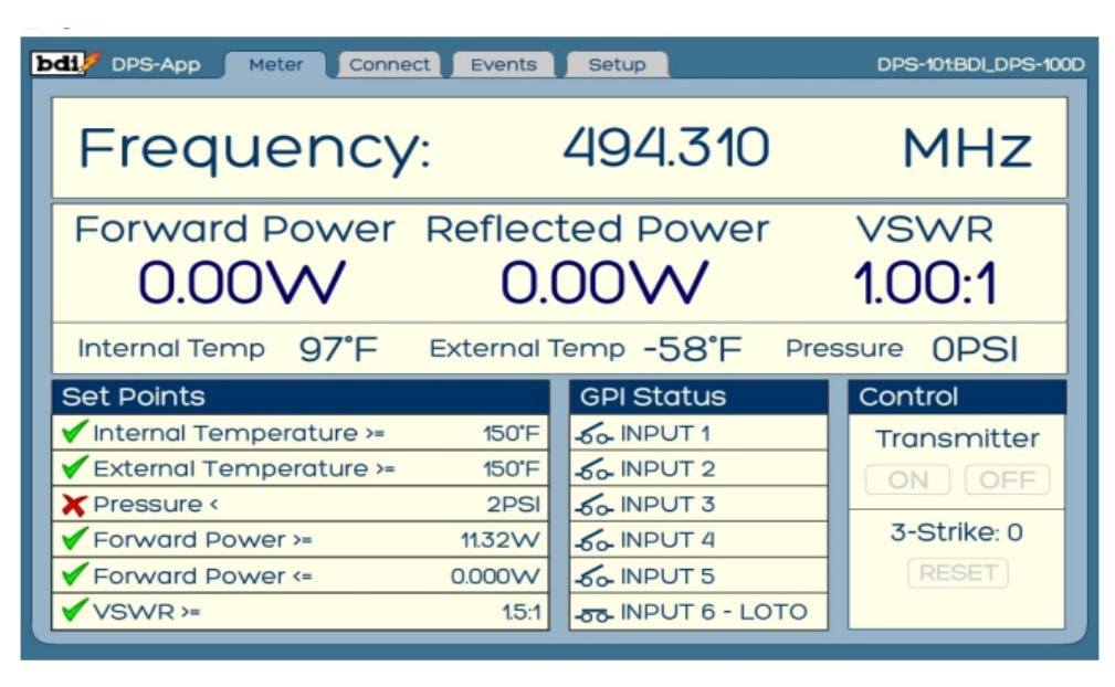
The DPS-100D Series power meters are supplied with an easy to read main screen for all important parameters including power, VSWR, general purpose input status, 3-Strike VSWR Protection System™, two temperature indications and transmission line pressure indication. All of this on a single, easy-to-read screen. There is also provision for controlling the On/Off function of a transmitter with the two available programmable relays. Of course the DPS-100D series power meters are SNMP v2 compatible so they interface seamlessly with all modern remote control systems and third part SNMP software packages.
![]()
![]()
- Electrical Specifications: Frequency Range: Sensor: 0.5 MHz—4GHz—Model Dependent
- Through Line VSWR: 1.05:1 or better Coupled Port
- Directivity: 30 dB or better
- Impedance: 50 ohms through port
- Measurement Type: True RMS – Suitable for CW, multi carrier and high crest factor digital RF signals such as AM/FM, 8 VSB (ATSC 1.0/3.0 ), DVB-T, ISDB-T,DTMB, IDRM, IBOC (in band on channel Ibiquity standard). DAB, etc.
- Accuracy: +/- 5% of indicated reading maximum error within instrument dynamic range.
- Dynamic Range: 40db or better Linear dynamic Range.
- Power Measurement Range 0 – 2.5 Mega watt Model and Coupler Line Size Dependent
- Measurement Capabilities: Forward and Reflected RF Power, Transmission line temperature (Deg F / Deg C user selectable) 1 each – External Temperature and line pressure sensors. 6 – User configurable closure inputs. (typically patch panels, lock-out/tag-out) Integrated Digital Display: 2 Line x 16 character LCD display of Fwd/Ref RF Power, Temperature (x2), Line Pressure Dedicated Icons for VSWR fault, Alert Status, Communications Status, RF Power High/Low thresholds, DC power input status and LAN connection status.
- Communications Interfaces: Ethernet, RS-485, Network Protocols: SNMP, SMTP, TCP/IP, UDP, SNTP, 2 – Configurable VDC proportional power outputs, 2 – Form C configurable interlock/status relays/On/off 2 – Configurable External GP inputs for fault reset 12 Position Termi nal Block: 6 – Configurable General Purpose Inputs for lock out tag out, patch panel, external interlock strings, etc. Ext. Temperature Sensor Input3 – Position terminal block mates with BDI TMP-100 T
- Physical Specifications:
Sizes: N, DIN, 7/8” 1-5/8”, 3-1/8” EIA, 4-1/16” Myat standard, 4-1/16” Dielectric standard, 6-1/8”, 9” and 12” special order. Flanged – One fixed, one swivel - Environmental Specifications:
Operating Temperature: ‐25°C to +55°C
Storage Temperature: ‐60°C to +85°C
Humidity: 95% Non‐Condensing
Xenirad
Xenirad 1/4 Shorting Stub for Coaxial Lighting Protection (See Full Page). The Ultimate in Coaxial Lightning Protection! A simple way to protect your transmitter investment is available.
The 1/4 Wave Shorting Stub also referred to as a 1/4 wave shorted stub, connects between your transmitter and your antenna system to short the center conductor to ground providing an unmatched degree of lightning protection for your transmitter. The stub is virtually invisible to your transmitter offering negligible insertion loss and an input VSWR <1.01 with return loss values typically >50db. The stub is tunable which allows for fine antenna matching in the field. The frequency agile stub can be tuned across the band it is made for. EX: FM stub is tunable from 87 to 110 Mhz. Custom frequency requirements are welcomed as well as various connector options, Flanged/Un-flanged, 7/16 DIN, N etc. Stubs can be made in 50 or 75 ohm to fit your requirements.
- Capable of handling very high discharge currents.
- Excellent transmission characteristics.
- Maintenance free, no parts to replace after a discharge event.
- Acts as a broadband filter and reduces AM signals by >30db at sites where an AM and FM are co-located.
- Stubs can be made for all power levels and frequency requirements including STL and RPU applications and in a variety of connector options.
- Excellent protection for both transmitters and receivers.
- Handmade here in the USA
- Cheap insurance against lightning damage when considering off air time and repair cost
- Stubs can be made in 7/8, 1 5/8, 3 1/8 with power handling capabilities up to 50KW.


")